- Original Article
- Open access
- Published:
Performance improvement of 5G positioning utilizing multi-antenna angle measurements
Satellite Navigation volume 3, Article number: 17 (2022)
Abstract
Time delay-based the 5th Generation Mobile Communication Technology (5G) positioning is a main method to perform high-precision positioning in Global Navigation Satellite System (GNSS) denied areas. However, in practical applications, the occlusion of signals in a complex environment results in few observable base stations, which affects the reliability and accuracy of positioning. The aim of this study is to improve the performance of the 5G positioning in complex environments with an insufficient number of observable base stations. First, the Angle of Departure (AOD) capability of multi-antennas is integrated into Multi-Round-Trip-Time (Multi-RTT) positioning, establishing a novel 5G RTT/AOD positioning model. Then, the influencing factors of positioning performance, including the Dilution of Precision (DOP) and the accuracy of the AOD measurements, is analyzed. The relationship between DOP and RTT/AOD positioning accuracy is deduced. Afterwards, simulation experiments are performed on 5G positioning with the Multi-RTT and RTT/AOD methods in two scenarios with good and complex environments. The theoretical analysis and experimental results show that 5G positioning with the RTT/AOD method increases the horizontal and vertical accuracies by approximately 25 and 65%, respectively, compared with the Multi-RTT method. The positioning reliability is also greatly improved. The proposed model can well solve the inefficiency of 5G positioning with the RTT method in scenarios where the number of base stations is less than three.
Introduction
In addition to its communication functions, the 5th Generation Mobile Communication Technology (5G) has many excellent features, such as its ultra-dense base stations and the Angle of Departure (AOD) capability of multi-antennas, required for positioning (3GPP TS38.305, 2020;3GPP TS 48.455 2019). As the communication standard maker, the 3rd Generation Partnership Project (3GPP) has been committed to adding positioning capabilities to the communication standards (Keating et al., 2019). In Release 16 TS38.855, 3GPP has defined multiple positioning methods (Liu et al., 2017), including Down Link Time Difference of Arrival (DL-TDOA), Up Link Time Difference of Arrival (UL-TDOA), Multi-Round-Trip-Time (Multi-RTT), Down Link Angle of Departure (DL-AOD), Up Link Angle of Arrival (UL-AOA), and Enhanced Cell Identity (E-CID). Among them, time delay and angle are the main signal characteristics used for 5G positioning. The time delay method can achieve better positioning capability (Chaloupka, 2017) and is the key to expanding positioning capability from the Second-Generation mobile network or service (2G) to the Fourth-Generation of wireless standards for cellular systems (4G), such as the Observed Time Difference of Arrival (OTDOA) method supported by Idle Periods in Down Link (IPDL) in Code Division Multiple Access 2000 (CDMA2000) and Positioning Reference Signal (PRS) in Long-Term Evolution (LTE). The core objective is to improve the accuracy of time delay observation.
The high-precision positioning based on time delay observations has been widely studied. However, high-precision time delay observations are dependent on the synchronization accuracy of 5G base stations. The realization of sub-meter-level positioning accuracy requires nanosecond time synchronization accuracy (Chaloupka, 2017). Considering time synchronization, at least four observable base stations are required for Three Dimensional (3D) positioning using the TOA-based methods. Multi-RTT 3D positioning, which is immune to the influence of time synchronization, requires at least three observable base stations. Yet, the probability of meeting this requirement is quite low in practical applications. In the literature (Dammann et al., 2015), the case where at least one of the three base stations is non-line-of-sight is defined as an outage. For three base stations with spacing of 100 m, the probability of the outage is 82.2%.
Given the increasing communication needs and demands, 5G base stations will include a large-scale antenna array in the future to expand the communication capacity with beamforming technology (Wen et al., 2019; Wymeersch et al., 2017). This innovation will also enable the 5G base stations to have a certain angle measurement capability and realize AOD-based 5G positioning. AOD-based positioning is different from Multi-RTT positioning in two aspects: one is the AOD 3D positioning needs at least two observable base stations, while Multi-RTT positioning three observable base stations. The other is the vertical accuracy is better than the horizontal accuracy in AOD positioning, whereas the horizontal accuracy is better than the vertical accuracy in Multi-RTT positioning. At present, the angle-based positioning algorithms can be divided into three types. One is the iterative least squares algorithm based on Causs-Newton method. This algorithm uses the iterative least squares method with user initial position (Torrieri et al. 1984). The model of this algorithm is simple, but greatly affected by the initial position. The second one is an algorithm based on grid matching, which matches the theoretical value of an angle with the measurements at all possible positions and takes the position with the highest matching score as the user position (Cominelli et al., 2019). This algorithm is often very time consuming. The third one is the closed-form solution algorithm, that is, positioning is achieved by establishing linear or pseudo-linear equations of angle measurements by using the geometric relationships among angle measurements, user position, and base station position (Wang et al. 2015; Monfared et al., 2018). This algorithm model is complex, but without iteration and less affected by initial position.
Several scholars carried out the theoretical analysis and experimental verifications of the time delay/angle fusion positioning to improve the positioning reliability and accuracy. Most studies focus on the TOA/AOD fusion positioning instand of RTT/AOD fusion positioning. The former is suffered by the time synchronization between the base stations and users compared to the latter. The research on 5G positioning shows that positioning error below one meter can be achieved with joint TOA and AOD methods (del Peral-Rosado et al., 2016). Shahmansoori et al. (2017) derived the Cramér–Rao Lower Bound (CRLB) for TOA/AOD-based positioning using a single transmitter in the presence of scatters. In terms of experimental methods for 5G positioning, Koivisto et al., (2017a, b; 2018) designed a simulation experiment combining AOD and TOA, detailing clock model, channel modelling, and simulation scenario setting. He also proposed a two-stage Extended Kalman Filter scheme to extract observations and estimate position. To analyze positioning performance, Li et al. (2018) calculated the CRLB with the TOA/AOD method for 2D positioning in the condition of a sufficient number of observable base stations. In addition, some scholars studied the fusion positioning of 5G TOA/AOD and GNSS based on the least squares approach and Helmert variance component estimation, and obtained the positioning results with the accuracy at meter level (Su et al. 2020; Sun et al., 2020). Compared with the TOA method, the TOA/AOD method can relax the strict time synchronization requirements of the positioning system. However, most of the above studies are experimental for or analyze the positioning performance in the condition of a sufficient number of observable base stations. They also fail to consider the effect of the AOD measurements on the reliability and accuracy of 5G positioning in such environments. In practical applications, especially in complex environments like indoors, the number of available 5G base stations is usually insufficient. Thus, the performance of 5G positioning will be significantly deteriorated.
In this study, the AOD capability of multi-antennas is integrated into 5G Multi-RTT positioning to test its efficiency. The main objective is to improve 5G positioning reliability and accuracy in a complex environment where the number of observable base stations is insufficient. The influence of the AOD measurements on the positioning performance is analyzed theoretically. Then, simulation experiments are carried out in two scenarios with good and poor observation environments, respectively, to compare the differences in the reliability and accuracy of 5G positioning before and after adding the AOD measurements. In this paper, we focus on the positioning rather than signal processing without considering the issues of the Non Line of Sight (NLOS) and multipath propagation of signals.
The remainder of this article is organized as follows. A 5G positioning model integrating the AOD and RTT methods is introduced in Section “5G positioning model integrating RTT/AOD”. The influencing factors of positioning performance, including the Dilution of Precision (DOP) and the accuracy of AOD measurement, are analyzed in Section “Positioning performance analysis”. Simulation experiments are conducted in Section “Experiment and results” to compare the positioning performances before and after adding the AOD measurements. Finally, the conclusions are provided in Section heading “Conclusions”.
5G positioning model integrating RTT/AOD
The basic principle commonly used in 5G positioning is similar to that in GNSS. It measures the distance between a base station and a user with the time delay and calculates the user position by multi-station intersection (Groves, 2015). 5G communication system uses Orthogonal Frequency Division Multiplexing (OFDM) signal based on cyclic prefix as 5G communication signal. Likewise, the PRS signal used to generate TOA observations is thus constructed. The PRS signal sequence of the downlink is a pseudo-random sequence generated by a Gold sequence with a length of 31. The user will receive a PRS signal for relevant detection to get the delay information of each base station. Using the up-link TOA \(t_{{\text{up - link}}}^{{{\text{TOA}}}}\) and the down-link TOA \(t_{{\text{down - link}}}^{{{\text{TOA}}}}\), we can construct the RTT \(t_{{{\text{RTT}}}}\) as follows:
As we can see, \(t_{{{\text{RTT}}}}\) is not affected by the time synchronization in (1). Without considering the NLOS and multipath propagation of the signal, the \(t_{{{\text{RTT}}}}\) between the user and each base station multiplied by the speed of light generates the distance. Assuming that \(\left(x,y,z\right)\) is the coordinates of the user to be estimated, \(\left({x}_{i},{y}_{i},{z}_{i}\right)\) is the coordinates of base station \({s}_{i}\), and \({t}_{i}\) is the RTT observation between base station \({s}_{i}\) and the user. The distance between the user and base stations can be expressed as
where \(c\) is the speed of light. When the accuracy loss caused by linearization is ignored, the linearized observation equations of Multi-RTTpositioning can be obtained as
where \({\varvec{X}}\) is the state vector, \({\varvec{Z}}\) is the observation vector, \({\varvec{H}}\) is the transition matrix, and \({\varvec{V}}\) is the observation error vector. These variables can be respectively expressed as.
where \(\left({x}_{0},{y}_{0},{z}_{0}\right)\) represents the user’s initial coordinates, and \(\delta {t}_{i}\) is the observation error of time delay. \({l}_{i,3d}\) is the 3D distance between the user’s initial position and base station, which is defined as
Following the observation equation of Multi-RTT positioning, a base station can only provide one RTT observation, and therefore to solve for 3 unknown coordinates at least three base stations are needed.
A 5G positioning model integrating RTT and AOD is proposed to improve the 5G positioning performance in the situation of insufficient base stations. AOD observations are obtained by the channel estimation algorithm using Channel State Information Reference Signal (CSI-RS) and the antenna information of transmitter and receiver. In this model, the azimuth AOD, vertical AOD, and signal propagation delay of 5G signal are expressed as \({\alpha }_{i}\in (-\uppi ,\uppi ]\), \({\beta }_{i}\in (-\frac{\uppi }{2},\frac{\uppi }{2}]\), and \({t}_{i}\), respectively. The relationship among time delay, angle observation, and user’s coordinates can be expressed as.
Following the above equation, one base station can provide three observations. Thus, positioning can be carried out with a single base station. Similarly, the observation equation of RTT/AOD positioning in the form of (3) can be obtained, where the observation vector \({\varvec{Z}}\), transition matrix \({\varvec{H}}\), and observation error vector \({\varvec{V}}\) can be respectively expressed as
where \(\updelta {\alpha }_{i}\) and \(\updelta {\beta }_{i}\) indicate the observation errors of the azimuth and vertical angles, respectively. \({l}_{i,2d}\) is the 2D distance between the user’s initial position and base station, which is defined as
In Multi-RTT and RTT/AOD positioning, the weight matrix \(P\) is set as the reciprocal of the variance of the observations. Then the user’s final coordinates \(\left(x,y,z\right)\) can be obtained through the iterative least square estimation as
Positioning performance analysis
In Multi-RTT positioning model, the main factors that affect the positioning performance include the number of base stations, distribution of base stations, and accuracy of observations. Assuming the estimated error of the state vector \({\varvec{X}}\) is \(\Delta {\varvec{X}}\), after ignoring and simplifying the second-order error term, the relationship between the estimated error \(\Delta {\varvec{X}}\) and the observation error \({\varvec{V}}\) can be obtained as
where \({{\varvec{H}}}_{t}\) is calculated by bringing in the true value of the user’s coordinates in the formula for calculating the transition matrix \({\varvec{H}}\). The time delay observations are assumed to be independent of each other and satisfy the zero-mean Gaussian distribution with the variance of \({{\sigma }_{t}}^{2}\). Accordingly, the accuracy of the 3D position estimation based on Multi-RTT positioning Root Mean Square (RMS) \({s}_{\mathrm{RMS}}^{\mathrm{RTT}}\) can be written as
\({d}_{\mathrm{DOP}}=\sqrt{\mathrm{tr}\left\{{\left({{{\varvec{H}}}_{t}}^{\mathrm{T}}{{\varvec{H}}}_{t}\right)}^{-1}\right\}}\) is completely determined by the number of base stations and the geometric relationship between the user and base stations. Thus,
When the accuracy of time delay observation is the same, the smaller the \({d}_{\mathrm{DOP}}\), the higher the accuracy of position estimation will be.
In RTT/AOD positioning, vector \({\varvec{V}}\) is a column vector composed of angle and time delay observation errors. Assuming that each observation error is independent, the accuracy of the 3D position estimation RMS \({s}_{\mathrm{RMS}}^{\mathrm{RTT}/\mathrm{AOD}}\) can be written as
The weighted matrix \({\varvec{P}}\) in (18) includes time delay accuracy and angle measurement accuracy. Thus, the relationships among \({s}_{\mathrm{RMS}}^{\mathrm{RTT}/\mathrm{AOD}}\), \({d}_{\mathrm{DOP}}\), and observation accuracy are no longer linear (Han, 2014).
In (16) and (18), the RMS represents the accuracy of the Weighted Least Square (WLS) estimated user’s position. Because WLS estimation belongs to a minimum variance estimation, when the initial coordinates of the user are equal to the true coordinates, the a posteriori estimated variance matrix of WLS is the inverse of the Fisher information matrix, which is consistent with the definition of Cramér-Rao Bound (CRB).
As shown in Section “Appendix”, \({s}_{\mathrm{RMS}}^{\mathrm{RTT}/\mathrm{AOD}}\) is smaller than \({s}_{\mathrm{RMS}}^{\mathrm{RTT}}\). Thus, the addition of AOD improves the accuracy of position estimation. One can see if the accuracy of time delay \({\sigma }_{t}\) and the \({d}_{\mathrm{DOP}}\) are the invariant, the higher the accuracy of angle measurements, the higher the accuracy of position estimation will be.
The addition of AOD reduces the influence of the distribution of base stations on positioning results. In a complex environment, the number of base stations that can be observed by the user is small, and the distribution of base stations is poor. Accordingly, the addition of AOD is conducive to the accuracy and reliability of 5G positioning. The following part will analyze the influence of the AOD on positioning accuracy and reliability.
Influence of AOD on positioning accuracy
The influence of the distribution of base stations on positioning accuracy can be measured by \({d}_{\mathrm{DOP}}\) value. For example, in the 2D Multi-RTT positioning, assuming that the number of base stations is \(N\), and \(\left(\mathrm{cos}{\theta }_{i},\mathrm{sin}{\theta }_{i}\right),{\theta }_{i}\in (-\uppi ,\uppi ]\) represents the relative position from the \(i\) th base station to the user, then
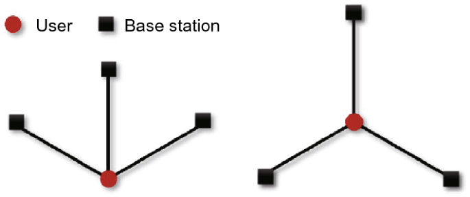
Taking 3 base station as an example, the connections between base stations and a user divide the space around the user into three sectors with the sector angles denoised as \({\alpha }_{1}\), \({\alpha }_{2}\), and \({\alpha }_{3}\). When \({\alpha }_{1}={\alpha }_{2}=60^\circ ,{\alpha }_{3}=240^\circ\), or \({\alpha }_{1}={\alpha }_{2}={\alpha }_{3}=120^\circ\),\({d}_{\mathrm{DOP}}\) has a minimum value \(\frac{2\sqrt{3}}{3}\), corresponding to the optimal distribution of three base stations, as shown in Fig. 1.
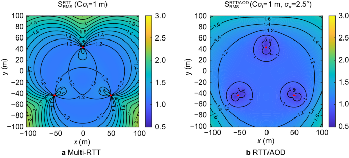
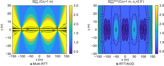
The positioning accuracy with Multi-RTT and RTT/AOD obtained by the user under the optimal distribution of three base stations (equilateral triangle distribution) and with the accuracy of RTT and AOD measurements being 1 m and 2.5°, respectively, is shown in Fig. 2, where the red triangles stand for the fixed base stations with the spacing of 100 m between them. The above values are typical for mathematical analysis, but not real in an urban area, even in an UMi scenario. For Multi-RTT positioning and RTT/AOD positioning, the users near a base station can be positioned with an accuracy better than 1.4 m. Compared with the positioning accuracy based on RTT, the area where the accuracy is better than 1.4 m is expanded for RTT/AOD positioning.
Influence of AOD on positioning reliability
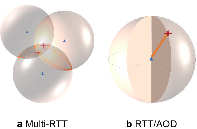
Generally, 3D positioning involves three unknown parameters. In Multi-RTT positioning, each base station can only provide one RTT observation, and thus at least three base stations are needed. The positioning principle is shown in Fig. 3(a). In RTT/AOD positioning, a base station provides three observations: distance, vertical angle, and azimuth angle. Therefore, only one base station is enough for positioning, as shown in Fig. 3(b). The addition of AOD reduces the the minimum number of base stations and can effectively improve the positioning reliability when the number of observable base stations is small.
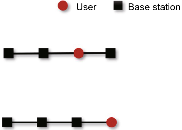
For the details, refer to Section “Influence of AOD on positioning accuracy” When \({\alpha }_{1}={\alpha }_{2}=180^\circ ,{\alpha }_{3}=0^\circ\) or \({\alpha }_{1}=360^\circ ,{\alpha }_{2}={\alpha }_{3}=0^\circ\), \({d}_{\mathrm{DOP}}\) value is the maximum and approaches infinity, which corresponds to the worst distribution of three base stations, as shown in Fig. 4.
In the worst distribution of the three base stations, the base stations are in line with the user. The accuracy of Multi-RTT positioning and RTT/AOD positioning by users under the worst distribution of the three base stations is shown in Fig. 5. The user close to the connection of the base stations has poor accuracy in Multi-RTT positioning. Only when the user is far away from the straight line between the base stations vertically can the positioning accuracy of greater than 1.2 m be obtained. In RTT/AOD positioning, the accuracy for the users near the straight line between the base stations has been greatly improved from greater than 10 m to less than 2 m.
Some conclusions can be drawn below. In the same observation condition, the addition of AOD provides more observations resulting in higher positioning accuracy compared with Multi-RTT positioning. Moreover the addition of AOD reduces the number of base stations, lowers the influence of the poor distribution of base stations on positioning results, and improves the reliability of positioning in poor observation environments.
Experiment and results
The experiment was in the urban environment. To vertify the theoretical analysis results in Section “Positioning performance analysis”, we used a abstract model that is independent of any transmit power and bandwidth to perform simulations. This model focuses on the accuracy of observations and the spatial distribution of base stations, and ignores the 5G signal propagation. As described in introduction, we chose the LOS propagation of a signal without considering the existence of scattering points and multipath signals. This will allow us to concentrate on the effect of angle observations on the Multi-RTT positioning.
Verify the influence of observation accuracy on positioning accuracy
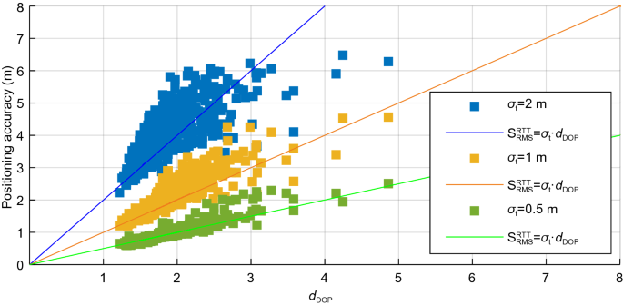
In the previous section, the theoretical relationship between positioning accuracy and observation accuracy was deduced. Specifically, the addition of AOD can improve the positioning accuracy. In this section, this finding will be verified through simulation experiments. In the proposed simulation scenario, the number of base stations follows the uniform distribution between 3 and 12, and the theoretical positioning accuracy corresponding to different observation accuracy can be obtained. The initial coordinates of the user is the average coordinates of the base stations used in positioning. The realistic positioning accuracy is determined by comparing the estimated position with the true position. The experiment was carried out 100 times to eliminate contingency, and the standard deviation of the 3D position error in each repeated experiment was calculated as the realistic positioning accuracy. The 3D positioning accuracy when the accuracy of RTT measurements is 0.5, 1, and 2 m, respectively, is shown in Fig. 6, where the straight lines indicate the theoretical RMS values, and the scatters indicate the 3D positioning accuracy of experiment results.
The experimental results show that the 3D positioning accuracy is significantly correlated with the accuracy of observations, consistent with the theoretical formula, that is, the 3D positioning accuracy is equal to the \({d}_{\mathrm{DOP}}\) value times the accuracy of observations. In addition, because the \({d}_{\mathrm{DOP}}\) value is greater than 1, the positioning accuracy is lower than the observation accuracy.
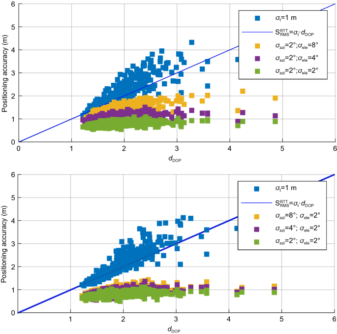
The effects of different observation accuracies on 3D positioning accuracy after adding AOD are shown in Fig. 7 and Table 1. When the accuracy of time delay measurements is kept the same, positioning accuracy after adding AOD is significantly improved. In addition, the correlation between the 3D position accuracy of RTT/AOD positioning and \({d}_{\mathrm{DOP}}\) becomes weak. This result indicates that the addition of AOD can lower the influence of poor \({d}_{\mathrm{DOP}}\) on positioning accuracy.
Compared with Multi-RTT positioning, after adding AOD with an accuracy of 2°, the average 3D positioning accuracy enhances from 2.033 to 0.798 m, with an improvement of 60.7%. This result indicates that the integration of AOD greatly improves the positioning accuracy.
The influences of the azimuth and vertical angles on the positioning results are compared, and the following findings are obtained. When the accuracy of the azimuth angle is 2° and the accuracy of the vertical angle is 8° and 4°, respectively, the accuracy improvements are all below 50% compared with Multi-RTT positioning. When the accuracy of the vertical angle is 2°, and the accuracy of the azimuth angle is 8° and 4°, respectively, the accuracy improvements are all above 50% compared with Multi-RTT positioning. Accordingly, the influence of the accuracy of the azimuth angle on positioning accuracy is greater than that of the accuracy of the vertical angle.
Verify the influence of the number of base stations on positioning accuracy
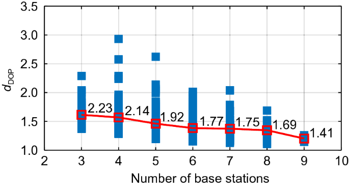
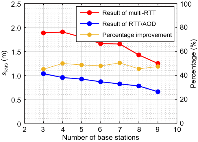
This section involves simulation experiments with the proposed number of base stations changed to verify its influence on positioning accuracy. The experimental results are shown in Figs. 8 and 9. The positioning accuracy with different numbers of base stations is shown in Fig. 8, and the changes in the positioning accuracy after adding AOD are shown in Fig. 9. As the proposed number of base stations increases, the average \({d}_{\mathrm{DOP}}\) gradually decreases. Similarly, as the number of base stations increases from 3 to 9, the accuracy enhances from 1.9 to 1.2 m in Multi-RTT positioning and from 1.1 to 0.7 m in RTT/AOD positioning. Overall, as the number of base stations increases, the positioning accuracy of Multi-RTT and RTT/AOD is improved. From the perspective of accuracy improvement, the effect of adding angle information is significantly better than increasing the number of base stations. The addition of angle information improves the positioning accuracy by approximately 50%, regardless of the number of base stations used for positioning.
Positioning performance in a complex environment
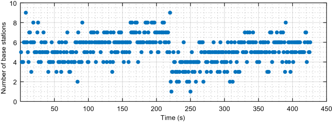
In complex scenes such as indoor and outdoor junctions and dense urban areas, the number of LOS signals will be reduced compared with that in the open environment due to the occlusion of buildings. In urban environments, we limited the number of base stations to 1–9 and also regarded the time as poor observation epoch when the number of base stations is not more than 3, otherwise good observation epoch. In the assumption of LOS propagation, the accuracy of observations is less affected by scene changes, so we believe that the accuracy of observations in complex scenes and good scenes are the same, i.e., RTT accuracy is 1 m, and AOD accuracy is 2°.
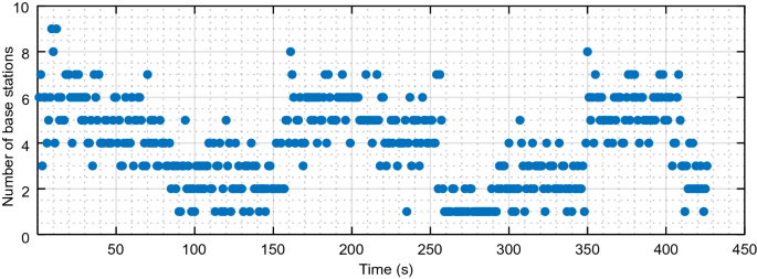
At least three base stations are required in Multi-RTT positioning, whereas RTT/AOD positioning needs only one base station. This section simulates a complex environment for further analysis. This environment often has less than three base stations during the positioning process. The number of base stations used for positioning at different epochs is shown in Fig. 10. The proportion of epochs with base stations less than three is 27.7%.
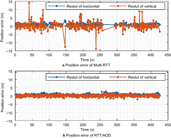
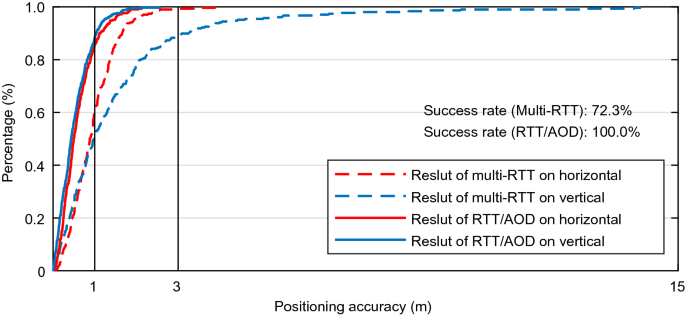
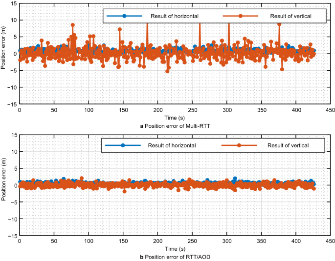
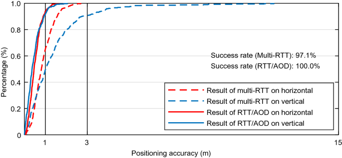
The sequence of horizontal and vertical position errors in Multi-RTT and RTT/AOD positioning is presented in Fig. 11. The statistical results, including the standard deviation of position error, the percentage of position error in each interval, and the percentage of epochs when the positioning converges are indicated in Fig. 12 and Table 2. Given the limitation of the minimum number of base stations, the results in Multi-RTT positioning are relatively sparse, especially in second 150 to second 350, when the number of base stations is insufficient. By contrast, continuous and dense results are exhibited by RTT/AOD positioning, even with an insufficient number of base stations.
In terms of positioning accuracy, after adding AOD, the horizontal and vertical accuracies are enhanced by approximately 27 and 65%, respectively. The reason for the greater enhancement in the vertical accuracy is that the vertical angle can provide redundant observations for vertical positioning, and its observation accuracy is better than that of the azimuth angle.
After adding AOD, the percentage of the epochs with a smaller position error has been greatly improved. In addition, the positioning reliability has been enhanced.
To sum up, the addition of AOD has the following advantages. It reduces the demand for the number of base stations, increases the proportion of the epochs for successful positioning, expands the scope of application of 5G positioning, and improves the accuracy and reliability of positioning in a complex environment.
Positioning performance in a good environment
This part will compare the changes in positioning accuracy before and after adding AOD when the observation condition is good. The number of base stations is around 3–7, and the proportion of the epochs with base stations less than three is only 2.8%, as shown in Fig. 13.
The positioning accuracy before and after adding AOD is compared in a good environment. The error sequence is presented in Fig. 14, and the statistical results are listed in Fig. 15 and Table 3. The position error sequences obtained by Multi-RTT and RTT/AOD positioning are continuous. However, in RTT/AOD, the frequency of large errors has been reduced. Finally, the horizontal and vertical accuracies are improved by approximately 39 and 76%.
Conclusion
In this study, we conducted the following investigation to improve the positioning performance of 5G with an insufficient number of observable base stations. First, the AOD capability of multi-antenna is integrated into 5G positioning, establishing a novel 5G positioning model with an intergartion of AOD and RTT. Then, the influences of the distribution of base stations and the accuracy of angle measurement on positioning accuracy are examed with theoretical analysis. The relationship between RTT/AOD positioning and base stations geometry distribution is deduced and analyzed theoretically. In a complex environment where the number of observable base stations and the distribution of base stations is not favorable, the addition of AOD measurements is tested to determine if the positioning accuracy and reliability can be imrpoved. Accordingly, simulation experiments are carried out in two scenarios with good and complex environments, respectively, to compare the difference before and after adding the AOD measurements. The experimental results show that the addition of the AOD measurements significantly improves the positioning accuracy. Specifically, the horizontal accuracy is improved by more than 25%, and the vertical by more than 65%. Adding the AOD measurements also affects the positioning reliability. The complete positioning capacity is realized, and the problem that the RTT measurements along cannot position in the scenario with less than three base stations is solved.
However, considerable work remains to be further studied to improve the performance of 5G positioning in a complex environment. Two aspects can be foreseen. One is to use the \({d}_{\mathrm{DOP}}\) value to select favorable base stations and determine if the AOD measurements are needed. The other is 5G positioning can be fused with inertial navigation for the application in the places with no observable 5G base station for a short period, such as in tunnelsand other occluded areas.
Availability of data and materials
The other data used in this study are available from the corresponding author upon request.
References
Chaloupka, Z. (2017). Technology and standardization gaps for high accuracy positioning in 5G. IEEE Communications Standards Magazine, 1(1), 59–65.
Cominelli, M., Patras, P., & Gringoli, F. (2019). Dead on arrival: An empirical study of the Bluetooth 5.1 positioning system. In: Proceedings of the 13th international workshop on wireless network testbeds, experimental evaluation & characterization. Los Cabos, Mexico, pp. 13–20.
del Peral-Rosado, J. A., López-Salcedo, J. A., Kim, S., & Seco-Granados, G. (2016). Feasibility study of 5G-based localization for assisted driving. In: Proceedings of the 2016 International conference on localization and GNSS (ICL-GNSS). Barcelona, Spain, pp. 1–6.
Dammann, A., Raulefs, R., & Zhang, S. (2015). On prospects of positioning in 5G. In: Proceedings of the 2015 IEEE International conference on communication workshop (ICCW). London, UK, pp. 1207–1213.
3GPP TS 38.305. (2020). NG Radio Access Network (NG-RAN); Stage 2 functional specification of User Equipment (UE) positioning in NG-RAN (Release 16).
3GPP TS 38.455. (2019). NG-RAN; NR Positioning Protocol A (NRPPa) (Release 15).
Groves, P. D. (2015). Principles of GNSS, inertial, and multisensor integrated navigation systems, 2nd edition [Book review]. IEEE Aerospace and Electronic Systems Magazine, 30(2), 26–27.
Han, T. (2014). Research on GNSS multi-system satellite selection strategy. Ph.D. Thesis, Shanghai Jiaotong University, China.
Keating, R., Säily, M., Hulkkonen, J., & Karjalainen, J. (2019). Overview of positioning in 5G new radio. In: Proceedings of the 2019 16th International symposium on wireless communication systems (ISWCS).Oulu, Finland, pp. 320–324.
Koivisto, M., Talvitie, J., Costa, M., Leppänen, K., & Valkama, M. (2018). Joint cmWave-based multiuser positioning and network synchronization in dense 5G networks. In: Proceedings of the 2018 IEEE Wireless Communications and Networking Conference (WCNC). Barcelona, Spain, pp. 1–6.
Koivisto, M., Costa, M., Werner, J., Heiska, K., Talvitie, J., Leppänen, K., & Valkama, M. (2017a). Joint device positioning and clock synchronization in 5G ultra-dense networks. IEEE Transactions on Wireless Communications, 16(5), 2866–2881.
Koivisto, M., Hakkarainen, A., Costa, M., Kela, P., Leppanen, K., & Valkama, M. (2017b). High-efficiency device positioning and location-aware communications in dense 5G networks. IEEE Communications Magazine, 55(8), 188–195.
Li, Y. Y., Qi, G. Q., & Sheng, A. D. (2018). Performance metric on the best achievable accuracy for hybrid TOA/AOA target localization. IEEE Communications Letters, 22(7), 1474–1477.
Liu, Y., Shi, X., He, S., & Shi, Z. (2017). Prospective positioning architecture and technologies in 5G networks. IEEE Network, 31(6), 115–121.
Monfared, S., Nguyen, T. H., Petrillo, L., De Doncker, P., & Horlin, F. Experimental demonstration of BLE transmitter positioning based on AOA estimation. In: Proceedings of the 2018 IEEE 29th Annual international symposium on personal, Indoor and mobile radio communications (PIMRC). Bologna, Italy, pp. 856–859.
Shahmansoori, A., Garcia, G. E., Destino, G., Seco-Granados, G., & Wymeersch, H. (2017). Position and orientation estimation through millimeter-wave MIMO in 5G systems. IEEE Transactions on Wireless Communications, 17(3), 1822–1835.
Su, W., & Deng, Z. (2020). Research on the weight distribution of helmert variance component estimation in Beidou+ 5G Integrated positioning. In: Sun J, Yang C, Xie J. (eds) China Satellite Navigation Conference (CSNC) 2020 Proceedings: Volume III. CSNC 2020. Lecture Notes in Electrical Engineering, vol 652. Springer, Singapore. https://doi.org/10.1007/978-981-15-3715-8_39.
Sun, C., Zhao, H., Bai, L., Cheong, J. W., Dempster, A. G., & Feng, W. (2020). GNSS-5G hybrid positioning based on TOA/AOA measurements. In: Sun J, Yang C, Xie J. (eds) China Satellite Navigation Conference (CSNC) 2020 Proceedings: Volume III. CSNC 2020. Lecture Notes in Electrical Engineering, vol 652. Springer, Singapore. https://doi.org/10.1007/978-981-15-3715-8_47.
Torrieri, D. J. (1984). Statistical theory of passive location systems. IEEE Transactions on Aerospace and Electronic Systems, 2, 183–198.
Wang, Y., & Ho, K. C. (2015). An asymptotically efficient estimator in closed-form for 3-D AOA localization using a sensor network. IEEE Transactions on Wireless Communications, 14(12), 6524–6535.
Wen, F., Wymeersch, H., Peng, B., Tay, W. P., So, H. C., & Yang, D. (2019). A survey on 5G massive MIMO localization. Digital Signal Processing, 94, 21–28.
Wymeersch, H., Seco-Granados, G., Destino, G., Dardari, D., & Tufvesson, F. (2017). 5G mmWave positioning for vehicular networks. IEEE Wireless Communications, 24(6), 80–86.
Acknowledgements
Not applicable.
Funding
This work was supported by the National Key Research and Development Program of China under Grant No. 2018YFC0809804, the National Science Foundation of China under Grant No. 41974038, and the major consulting research project of the Chinese Academy of Engineering(HB2020B13).
Author information
Authors and Affiliations
Contributions
WFG put forward the main ideas and ideas of the article, and YD completed the experiment, writing and analysis part of the article. All the authors read and approved the manuscript.
Authors information
Wenfei Guo is an associate professor at GNSS Research Center, Wuhan University. He received his PhD in Communication and Information Systems from Wuhan University in 2011. His research focuses on GNSS receivers and relevant signal processing technologies, including high precise timing receivers, GNSS-R receivers and anti-jamming receivers, etc.
Yue Deng received the B.S. degree in navigation engineering at the School of Geodesy and Geomatics, Wuhan University, in 2018. She is currently pursuing the M.S. degree in Navigation, Guidance and Control at the School of Geodesy and Geomatics, Wuhan University, China. Her area of interests includes indoor and outdoor positioning.
Chi Guo received the MEng and PhD degrees in computer science from Wuhan University, Hubei province, China. Currently, he is an associate professor at the national satellite positioning system engineering technology research center of Wuhan University. His current research interests include Beidou application, unmanned system navigation and location based services (LBS).
Shufeng Qi received the B.S. degree in Faculty of Geosciences and Environmental Engineering, Southwest Jiaotong University, in 2020. He is currently pursuing the M.S. degree in GNSS Research Center, Wuhan University, China. His area of interests includes 5G positioning and 5G/GNSS.
Jingrong Wang received the M.S. degree in surveying and mapping engineering from the State Key Laboratory of Information Engineering in Surveying, Mapping and Remote Sensing, Wuhan University in 2018. He is currently pursuing the PhD degree in Geodesy and Surveying Engineering at GNSS Research Center of Wuhan University. His current interests include indoor and outdoor positioning, and research on channel estimation algorithms in 5G systems.
Corresponding author
Ethics declarations
Competing interests
The authors declare that they have no competing interests.
Additional information
Publisher's Note
Springer Nature remains neutral with regard to jurisdictional claims in published maps and institutional affiliations'' (in PDF at the end of the article below the references; in XML as a back matter article note).
Appendix
Appendix
If the transition matrix and weight matrix of Multi-RTT positioning are \({{\varvec{H}}}_{t}\) and \({\varvec{P}}\), respectively, after adding an angle observation of precision \({\sigma }_{\alpha }\), the transition matrix and the weight matrix become \({{\varvec{H}}}_{t}^{^{\prime}}\) and \({{\varvec{P}}}^{^{\prime}}\).
In the matrix \({{\varvec{H}}}_{t}^{^{\prime}}\), the row vector corresponding to the angle observations is \({\varvec{h}}\). Then,
given that the weight matrices \({{\varvec{P}}}_{t}\) and \({{\varvec{P}}}^{^{\prime}}\) are the reciprocal of the observed error variance, and each observation is independent, \({{\varvec{P}}}_{t}\) can be decompressed into the product of two diagonal matrices as follows:
Singular value decomposition is performed for \({{\varvec{H}}}_{t}{{\varvec{R}}}_{t}\)
where \({\varvec{U}}\) and \({\varvec{V}}\) are orthogonal matrices, and \({\varvec{S}}\) is a diagonal matrix. By substituting (22) and (23) into (21) and making an orthogonal transformation, the following equations can be obtained:
Orthogonal transformation does not affect the trace of the matrix. Thus,
where \(k=\sum_{i=1}^{3}{\left(\frac{{v}_{j}}{{z}_{jj}}\right)}^{2}>0\), \(f=\sum_{i=1}^{3}\frac{{{v}_{j}}^{2}}{{z}_{jj}}>0\). Accordingly,
When m azimuth angles and n vertical angles exist, then
where corner marks \(\alpha\) and \(\beta\) denote azimuth angle and vertical angle, respectively. In (29), given that \({\sigma }_{\alpha }^{2}\), \(k\), and \(f\) are all positive real numbers, \({({s}_{\mathrm{RMS}}^{\mathrm{RTT}/\mathrm{AOD}})}^{2}<{({s}_{\mathrm{RMS}}^{\mathrm{RTT}})}^{2}\).
Rights and permissions
Open Access This article is licensed under a Creative Commons Attribution 4.0 International License, which permits use, sharing, adaptation, distribution and reproduction in any medium or format, as long as you give appropriate credit to the original author(s) and the source, provide a link to the Creative Commons licence, and indicate if changes were made. The images or other third party material in this article are included in the article's Creative Commons licence, unless indicated otherwise in a credit line to the material. If material is not included in the article's Creative Commons licence and your intended use is not permitted by statutory regulation or exceeds the permitted use, you will need to obtain permission directly from the copyright holder. To view a copy of this licence, visit http://creativecommons.org/licenses/by/4.0/.
About this article
Cite this article
Guo, W., Deng, Y., Guo, C. et al. Performance improvement of 5G positioning utilizing multi-antenna angle measurements. Satell Navig 3, 17 (2022). https://doi.org/10.1186/s43020-022-00078-y
Received:
Accepted:
Published:
DOI: https://doi.org/10.1186/s43020-022-00078-y
